June 30, 2010

So you can't afford it? Are you sure?

I'm noticing a trend amongst some audio enthusiasts. Some buy in haste, then sell quickly at a loss. Others are not so extreme, but are in a regular cycle of upgrading. I have a few ideas that could put that speaker you lust after within reach, but it could challenge your patterns of purchase. But if it means you can now afford something that was out of reach ...

Lifecycle costing

Over time, the quicker you upgrade, the more the item effectively costs. Ten one grand amps in ten years costs the same as one ten grand amp in that time. This is where some self control brings a return. So it's important to consider the lifecycle of your items.

Digital sources:
Medium term purchase.

Your DVD player is now obsolete and Blu-ray is now affordable. Buy one that is decent quality and run it as a digital transport and you should have no need to upgrade as long as it's working without problems. At least, not until it's lacking support of important features or Blu-ray becomes obsolete.

Preamps:
Long term purchase.

Power amps:
Long term purchase.

Surround processing/AV receivers:
Medium term purchase.

Surround processing is always changing, so a processor will never be long term. If you buy a receiver, the amps will have a longer life cycle but in many cases will be of limited capability. So it makes sense to buy a receiver for it's processing ability and features or buy a dedicated processor.

Speakers:
Long term purchase.

Speakers and power amps go together, and should be considered together. Your speakers should determine the amplifier chosen, not the other way around. Fortunately both are long term items and in many cases will be upgraded simply because you want better. If you have to cut corners, do it elsewhere.

Suggestions:
  • Limit spending on items with a shorter lifecycle
  • Focus spending on longer term items and if necessary delay purchasing speakers and amps until you can afford what you really want
  • Choose speakers and amplifiers at the same time, even if you can't buy them both at the same time
Focus spending where it makes the biggest difference

It's very easy to spend your money in a diffused way so that very quickly it disappears. The result is often a compromise on the items that matter most. If you become seduced by fancy cables and expensive well reviewed digital sources, it becomes difficult to invest seriously in speakers. As a general rule, your speakers should cost more than everything else. The more you spend on your system in total, the bigger the gap. For an entry level system around AU $4k, you should spend about half the total on speakers. For a higher end system over $20k it should be more like three quarters. In reality you can't go by the numbers, but this is a broad suggestion. If you have a $4k system where the cables cost more than the speakers, then sound quality has taken a back row seat.

* to be continued *

Tweeter pad - a simple tweak that might save your speakers

Here is a simple tweak that will make many budget speakers sound more natural (and even some not so budget speakers), as well as increase the power handling and reduce the chances of tweeter failure when pushed hard. It's called an L-pad and it's a very simple mod that anyone who is soldering iron handy can do. You simply need two resistors added to the crossover.

Too late: a TDL speaker that needs a pad

Recently I fixed a TDL RTL3 speaker that needed fixing. The tweeter often goes on this speaker. A late night party was too much for the tweeter, being pushed way too hard. I replaced the tweeter with a new pair and put an L-pad on to make it a bit more natural and also more robust. Does this look like too much power to you?


Read more about it here >

Why do I need one?

Most well designed speakers of conventional design have a tweeter that is more efficient than it needs to be. Often the designer will allow for this and use a pad, but in some cases the tweeter level is left unaltered so that the treble is emphasised. Often in a retail store with a short demo, customers will choose the speaker with slightly more treble or bass. Over time this becomes less appealing. If you have a speaker like this, a pad is a quick and easy fix.

You may prefer less treble than the designer.

You might also listen at higher levels, where it can be better to have reduced treble. This will also increase the power handling. A typical 3db pad will double the power handling of the tweeter.

How to calculate it

You need to know the nominal impedance of the tweeter. Often this will be shown on the tweeter. If you know the tweeter brand and model number then you can perhaps find a datasheet on the internet. You can measure the resistance of the voice coil with a multimeter when the tweeter is disconnected from the crossover. Please note that this is the DC resistance and gives an indication of the impedance which will be higher.

Examples
Vifa D27TG R= 4.6ohm, impedance = 6 ohm
Peerless HDS R= 5.6ohm, impedance = 8 ohm
Peerless 100 HDT R= 6.8ohm, impedance = 8 ohm
Scan Speak Revelator R= 3ohm, impedance = 4 ohm

Use an L-pad calculator to work out the value of the two resistors.

L-pad calculator >

How much power?

Obviously you don't want 1/2w resistors. The power required depends on the amplifier used and the proportion of that power that the tweeter will see. Higher crossover points and steeper slopes will result in less power going to the tweeter. Let's work out an example.

100w amplifier
2nd order crossover at 3k

Above 3k, the tweeter will see 15% of the power so in this case 15w is the most that the tweeter will see. In normal use, the continuous power is more likely to be less than this so a pair of 10w resistors will be fine.

Soldering it in

Conect one in series and one in parallel with the tweeter. The pad should be inserted after all components involved in the high pass filtering components.

Correct
Amplifier > tweeter high pass > L-pad > Tweeter

Incorrect
Amplifier > L-pad > tweeter high pass > Tweeter

If done incorrectly, the L-pad will now see a full range signal and thus it's power rating will be inadequate. It will overheat and most likely fail.

Now evaluate by ear and see what you think. You might need to try different values. Most pads will be in the 2 - 4 db range. Less will be too subtle and more will rarely be required.

Ensure the resistors are securely soldered with a strong bond, then fix them to the crossover board with a hot melt glue gun, or with straps.

Conclusion - give it a go

Sometimes this simple tweak can save an upgrade. If you think your speakers are a little too bright, this could be the answer. It's simple and cheap. If your speaker already has a pad, but you want to increase the value, first find out their values, then with a pad calculator such as the one linked above you can work out the attenutation. Then work out the values for more attenutation.

June 29, 2010

Why you need a rumble filter

In this article I show why high pass filters, also referred to as rumble filters, are important. In the following simulations I'll demonstrate with a high excursion driver, the Exodus Audio Tempest X2. It has a one way xmax of 27mm. In the first example, we'll investigate a sealed box, where rumble filters often aren't considered necessary. 

Sealed box - 200L each with a Linkwitz Transform included, excursion plot:


Yellow - input power limited to avoid over excursion at 5 Hz
Blue - input power limited to avoid over-excursion at 20 Hz
Red - rumble filterinput power limited to avoid over-excursion at 20 Hz 

You can see that at high output (blue), the excursion gets out of control below 20 Hz, even in a sealed box. If we reduce the input power dramatically, we are safe to 5 Hz. This is probably good enough, however, the output as we will see in the next chart is limited. With a rumble filter, we can set up the system to avoid ever exceeding xmax. We can be sure our driver is safe.

SPL for the input levels previously shown


Yellow - input power limited to avoid over excursion at 5 Hz
Blue - input power limited to avoid over-excursion at 20 Hz
Red - rumble filterinput power limited to avoid over-excursion at 20 Hz 

You can see that output is much greater when a rumble filter is used. We've gained around 8 dB of output, which is equivalent to more than doubling up on drivers and box size. 

Now lets consider the same driver in a large low tuned vented box. 

Excursion


Orange - input power low to avoid over-excursion below 20 Hz
Green - no rumble filter
Magenta - rumble filter in place


Again we see much higher SPL as a result of using the rumble filter. We also avoid vent chuffing as a result of very high velocity in the vent. 


High end bandpass?

Is there such a thing as a high end bandpass? Bandpass subs get bad press. Mention one on an audio forum and you can expect to hear things like "boom box," "one note bass" and "poor transient response." Bandpass subs are the forgotten gems of subwoofer alignments.

What is a bandpass sub?

A bandpass sub uses a tuned acoustic chamber which provides acoustic filtering. The two most common types are shown below:

A 4th order bandpass (above left) can be thought of as a sealed box with an acoustic filter added. In the same way, a 6th order bandpass (above right) is a vented box with the same chamber added. The low end extension is similar to the sealed and vented equivalents, but the top end id different. An 8th order bandpass adds another acoustic chamber to both vents so that the final output of the sub comes through one vent.

Why bandpass?

The answer is simple - acoustic filtering. Conventionally a sub has a low pass crossover which is an electrical filter. An acoustic filter also filters out distortion products. Distortion makes it easier to localise a sub, so this filtering means that it becomes harder to pick the location of a bandpass sub. This means greater placement flexibility.

Covert sub placements

Sometimes the measured ideal placement for a sub doesn't work because it damages imaging. You might get a nice smooth in-room result with a sub in the rear corner, but you can localise sounds coming from the sub. A bandpass sub can potentially fix this. You might get away with that position - a bandpass sub is a covert one and it's location can be a well kept secret.

Here is an example of a sealed sub compared to a 4th order bandpass with the Peerless XLS 12:


The response is very similar, but the sealed box uses a 2nd order low pass crossover at 47 Hz while the bandpass has no electrical filter. Both have EQ for extension. You can see why below, where the raw response with no filtering is shown:


Where high output is desired over a narrow bandwidth, a bandpass can increase efficiency with a bigger box and give you more output than you could achieve with a vented box.

In part two I discuss 6th order bandpass subs.

June 27, 2010

Flareit - quiet vent design

In my previous post I introduced vent design to reduce compression - vents that won't chuff. Now I'll show you how to use a clever application I mentioned in this post.

Flareit.exe
Download here >


There is a simple process:

1. Start with a decent and sane design in WinISD where vent velocity isn't crazy

Non crazy starting points:

100mm vent with 20m/s
150mm vent with 25m/s

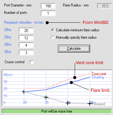
2. Enter the required vent velocity into the table and port diameter

Shown below under "Required velocities"

3. Click on calculate


The red line shows the absolute limit of the vent walls. It's generally best to aim for a lower velocity than shown here. When the velocity reaches this point the entire vent will experience compression and it's effectiveness breaks down.

In this example, I've let Flareit calculate the flare radius that is needed to meet the velocity requirement.

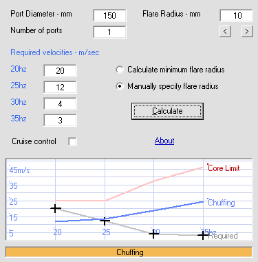
The blue line shows the limit based on the flare selected. The limiting factor is the lowest level, which could be either the red or blue line. If the blue line is above the red, then the radius is more than required - the vent walls are the bottleneck. If the blue line is below the red, then the flares are the bottleneck.

In this example, the port requires a flare on the ends with a 35.5mm radius.


If we manually enter a flare of 10mm with everything else the same, as shown above, you can see the result. The flare isn't enough and below 25 Hz the vent will chuff.

4. Choose your compromises

It's a juggling challenge. You will need to keep changing tuning, box size, vent diameter and flare radius until you get the best compromise. If you have a very large box as in the previous post, then compromise isn't necessary. If you use a driver like older versions of Peerless XLS, even though it has less than half the excursion, the challenge is far greater due to a small box. You may need to make the box bigger to get a vented design to work.

WinISD - how to design a vent that won't chuff

Vent design is one aspect that most don't handle very well. It's common for vented subwoofers to perform poorly when pushed. There are two problems:

1. Port compression - this is a reduction in output from the vent due to poor aerodynamics where high velocity compresses the output and reduces dynamics. As a result, the sub doesn't live up to its potential.

2. Port chuffing - an audible and distracting sound as vent velocity becomes extreme. It can be louder than the bass itself. These two problems are in fact one problem to a different extent.

Typically, many will follow a basic rule of thumb, such as using a 4" vent for a 12" driver, 5" for a 15" and 6" for an 18" driver. Others go by the velocity, aiming for arbitrary numbers like 34 m/s. This is a very hit and miss approach and I don't recommend it for anyone serious enough to design and build their own subwoofer. Just a little extra effort and you can design a high performance vented subwoofer. If this seems like too much effort, then I suggest a sealed design.

A few basics

The performance of the vent is determined by the velocity and the aerodynamics of the vent itself.

Port velocity is increased by:
  • larger drivers
  • high excursion
  • reducing the diameter of the vent
Our first challenge is to keep the velocity as low as possible. Once we have chosen our driver, when using all of its available displacement (excursion x piston area) we want to make sure the velocity in the vent is workable. We can reduce the velocity by:
  • increasing the vent diameter
  • using a rumble filter below tuning
  • lowering tuning
Normally we would choose the box size and tuning based on other factors. We should also consider a rumble filter necessary, otherwise we will often have an unworkable vent.

Note: commercial subs often use high excursion subs in a sealed box or lower excursion drivers with a vented design which tends to avoid making the vent design critical. It's not common to see too many designs with very high excursion drivers vented. Typically there are too many compromises involved. Also keep in mind that many subs claiming to use high excursion drivers have an xmax of around 12mm. Frankly, subwoofers have progressed a long way since 12mm xmax was impressive.

Increasing vent diameter. Sounds like a great solution, but this makes our vent longer. As soon as you make the vent big enough for your 25mm xmax driver, you have something that is huge. Oops! Now this is where we want to start getting away with higher velocity. Now we work on aerodynamics.

If we build a lazy vent, with no flares on the ends, it will chuff even with low velocity ie 7m/s. Let's say we have a 100mm vent. Add a flare with an 18mm radius and we can now live with around 10m/s. If we increase that radius to around 50mm then we can now get up to 20m/s. At that point, we can't improve further because the vent reaches its "core limit" at which the vent walls will start to cause problems. To go to the next level, we need a bigger vent.

Stepping it up to 150mm, the core limit now goes up to 25m/s. If we start getting really fanatical, we might go for 200mm, just so we can say "my vent is bigger than yours!" At this point, we can deal with 34m/s.

So where am I plucking all these numbers from?
I have to give some credit where it's due. Bill Collison (Collo) did some experiments on vents to determine where chuffing becomes audible. He then used the results to create an application called Flareit. The numbers here all come from that application. If designing a vented subwoofer, I suggest you open up Flareit along with WinISD. It's an essential tool.

Download Flareit here >

Worked example

Driver: Exodus Audio Tempest X 15"
Box: 400L vented tuned to 16 Hz


With the right settings, we have a textbook result with -3 db points at 20 and 80 Hz. With around 800w we use up all of the xmax capability.


A rumble filter keeps excursion under control below tuning. The cone will be moving up to 54mm from peak to peak.

If we use a 100mm vent, we have a problem:


Vent velocity goes off the chart! 54 m/s. At that velocity your subwoofer will work quite well as a fan to keep you cool in summer, and it will be noisy and chuff like mad. Things change as we use a bigger vent.


Now we have something workable. What happens if we turn off the rumble filter?


Again we have a problem. Very low bass that is present in movies will cause chuffing.

Given that our box is very large, we can live with a bigger vent. This vent is only 400mm long, so we can easily go up to the next size and have very low compression.


Now we have very low velocity, and that means we don't have to pay as much attention to aerodynamics and more difficult to construct vents with large flares.

June 25, 2010

Active options


Considering the many challenges of passive crossover design, many DIY enthusiasts are running their speakers actively. The advantages are compelling:

  • ease of tweaking and making changes
  • far more powerful and advanced filtering and EQ options to precisely control the response
  • freedom from impedance and tolerance issues
  • much greater efficiency in using power
  • freedom to use low power amps such as valves and class A
  • cleaner sound at high output

Update: How do they sound?

In a recent series of listening tests, I had a chance to compare four different active options in two systems. Some of the results were surprising.


Active crossover listening tests >

Analogue vs digital

Siegfried Linkwitz uses analogue active filters in his speakers. The advantage is that no digital to analogue conversion is needed, although as the complexity of the crossover increases, any sonic intrusions are cumulative. To work in analogue, the crossover must be designed and soldered and this is quite involved. It's a custom solution just like a passive crossover and can't quickly be changed. Working in the digital domain, once the digital to analogue conversion is made, as many filters as the chip allows can be made, including time domain and phase related corrections. Digital crossovers and DSP are far more powerful, and can be quickly and instantly changed without making physical changes to the boards. For this reason DSP is the way of the future. It is possible to construct an entire system where there is only one digital to analogue conversion, in which case DSP becomes even more attractive. It's important to keep in mind that while in the digital domain, changes can occur that impact on sound quality.

DCX: a bells and whistles crossover

The first choice for many is Behringer. Ultradrive DCX2496 and Ultracurve DEQ2496.

These are low cost and powerful options. Ultradrive has 6 channels, allowing stereo 3 way or 2 way for mains and centre in a surround application. Each channel has many different EQ options. Ultracurve is a dedicated EQ unit with much more powerful EQ options. It can be used for response shaping and is powerful enough for EQ that deals with room modes. Ultradrive doesn't have enough EQ processing for difficult room modes.

Ultradrive is used by Emerald Physics in their highly regarded speakers using waveguides and pro drivers. BESL use Ultradrive in their speaker development process, and supply it for use with their speakers.

One of the very attractive features of DCX is digital delays. Each channel can be time-aligned. There is an auto-align feature that calculates the required delay. The delays assigned are not neceesarily what you might expect, and might not correspond to physical driver offsets. If you sit closer to one speaker, you can also correct for this. This feature can have a dramatic impact on imaging.

Downsides

These units use servo balancing which is necessary for professional use but not for home use. As a result, in the home noise is introduced into the signal chain and it would be better to have unbalanced lines. The power supply is also noisy switchmode. Some have argued that the DAC isn't the best quality. As a result of these downsides, many different upgrades are available, many of them costing more than buying the unit itself. The ability to upgrade does make it more desirable.

Having used both units I can say that you can get a very good result with them and that they can improve most systems. However, for a refined and high end system correctly set up in a dedicated room, I'd suggest something better is warranted.

DEQX: an advanced and complete option

For a serious high end system, the premium choice appears to be DEQX. The cost is much higher than Behringer, but it is more powerful and has been designed for high end systems, taking an input from a digital transport (CD/DVD/Blu-ray digital output) and also including a high end DAC and multi channel preamp. It has a remote unlike the Behringer units and very steep slopes as well as phase correction so that no time domain abberations are introduced.

DEQX is used by Legend Speakers in their top of the range active speaker Legend Tikandi. They also use it in their Big Red (Kumbar Wirri) speaker, which is available active and passive and the difference is described by Ed Kramer in a 6 Moons review, on the second page.

Hypex: a built-in system

Hypex have created a built in system that uses a plate amp module for each speaker and digital active crossover which is set up by PC. Simply run an output from your preamp into the plate amplifier built in to the speaker. This eliminates amplifiers in your AV rack and gives a nice neat solution.

Hypex AS2.100 >


This is similar to the solution used by Australian custom speaker manufacturer Aslan Acoustics in their R1 and R3 Reference speakers. Combined with their music server, you have a complete system with just two components. For surround sound you just need more power amps and surround speakers.

DIY analogue options

For those inclined to get into DIY, a good analogue solution is found at Elliot Sound Products. A PCB is supplied with instructions for a 3 way active analogue crossover. It's important to keep in mind, however, that this type of active crossover simply uses textbook LR filters. My experience has been that a well designed passive crossover is better because more sophisticated filtering is needed. The other options are more powerful in that regard. I currently have a similar active crossover that I don't use as it wasn't an improvement over the passive crossover. The slopes and crossover points are all fixed by the components and multiple changes damage the PCB tracks.

MiniDSP: low cost and flexible

A very appealing new option is now available - MiniDSP. They supply fully assembled DSP modules that can act as an active crossover and EQ unit at a very low price. You simply need to put together a power supply, which can be as simple as a plugpack, then mount it in a case. Digital I/O modules are available and each one has 4 channels to allow for stereo 2 way or 4 way for one channel. Essentially this has the same functions as the Behringer units at a much lower cost without the issues related to balanced lines and the power supply. The settings are configured with a PC.


UPDATE:
MiniDSP now provide a plug and play solution and the cost increase is minor. In fact if you purchased a box and connectors it would probably cost you more.


One of the key features of MiniDSP is it's flexibility. Do you want to use your own DAC? The board is designed to allow this and many other options you would often not have.

Allocator: a PC based powerful crossover

Another powerful solution is PC software based DSP and crossovers. One good option is the Frequency Allocator at Thuneau.com.


It is an 8 channel option that requires a good quality 8 channel sound card. The software itself is cheap, and the solution is made more affordable if using an existing PC, but the cost of the sound card should also be considered. In order to get the most out of it, most users will need to upgrade their sound card.

How does it compare to the other options? In terms of features and performance, it seems to be comparable to DEQX. It allows up to 8 channels and so it can be used for stereo 4 way and it also can perform phase correction unlike MiniDSP and Behringer DCX. It can be used also in a surround system, although this means using the Lite version and running multiple instances. Phase correct isn't included in that case. For those who want to also use their system for 2 channel, it might make sense to run the full version for the mains and use MiniDSP for the surrounds.

There are many other benefits in using a PC in the sound system. It can perform the functions of a PVR and stream downloaded audio and video content. A PC can be a good platform for storing and playback. In many cases the cost of a PC solution is far less than stand alone components. For many, however it comes down to the question of whether you want a PC in your sound system and if you can get past the idea that surely the sound quality from a PC can't be "high end."

Other options

CAD Audio active modules

This option was pointed out in my other active options page.

CAD Audio DSP modules >

I won't comment just yet as I haven't had a chance to investigate this option, but it does appear promising.

Next: which active option is right for me? >


Active crossover listening tests >

June 24, 2010

WinISD - entering new driver data


Entering new driver data is a little tricky in WinISD pro. As the numbers are calculated, if you simply enter in all the parameters as shown in the data sheet, it won't work. A simple thing like rounding off the numbers will mess it up. You can find detailed instructions in the help files, but my video tutorial will give you the gist quickly.

A few tips:

1. Enter in the parameters in the exact order shown

2. If one parameter is missing, let the program calculate it from the others

3. Let the program automatically calculate some of the parameters


1. First enter mms and cms then click in fs which will then be calculated

In the tutorial, fs but not cms is provided.

2. Enter sd, bl and re

3. Enter Rms or Qms

If you only have one, then click on the other after entering, so it will be calculated

4. Enter xmax and PE

This is required for max SPL charts. If you don't have the power handling, you might make a reasonable guess. You might also choose to enter "music power" which is typically twice the typical nominal RMS rating.

5. Do a quick check of Qts, VAS and SPL to see that they are reasonably close to the specs. Don't worry about small changes as they aren't critical.

Note: Don't enter Le (voice coil inductance). Often this will result in simulations showing early roll off. Some drivers have a fairly high inductance of around 4mH. This will cause significant roll off much greater than measurements show. A null value here is usually more accurate.

June 22, 2010

Bass horns

Do you want to experience the ultimate in tight accurate dynamic bass? You can't beat bass horns. Well, actually you can, but it takes a very extreme setup costing a great deal more. Out of curiosity I did a simulated comparison between the current LFE champion, the Exodus Audio Maelstrom 21", and a 15" Rythmik. The larger driver has nearly twice the excursion and more than twice the cone area and the coil can take much more power. But due to the wonders of bass horns, the smaller driver wins the output challenge horn loaded if we compare to a sealed or vented design. In fact, the 21" was limited to 114 db @ 20 Hz with a very high powered amplifier, while the Rythmik could hit 125 db at that point with only 370w. What's the catch? The tapped horn is huge. Both are excellent options, but the point is that horn loading can extract very surprising performance out of a driver, effectively turning a modest or small driver into a much bigger super driver.

3 types of horns

There are 3 basic types of bass horns:

1. Front loaded horn (FLH)
2. Back loaded horn (BLH)
3. Tapped horn (TH)

A conventional horn is a FLH. The driver has a small sealed chamber on one side, and a horn on the other side, starting with a throat typically half the area of the cone expanding out to the mouth which is many times the area. A back loaded horn has no sealed chamber. This means that the excursion has less control below tuning, and that output from both sides of the cone are used. This is useful for wider bandwidth use, but generally detrimental for bass horns with a limited bandwidth.

The third type of horn is slightly controversial. It is often argued that it is a transmission line or a bandpass. While there are similarities, tapped horns (THs) have their own traits and deserve their own category. They require different drivers and a different design approach and different tools to simulate. They give you a different response and I see no reason to paint them with the same brush.

Tapped horns vs front loaded horns

In general I would not use them for the same job. For the ultimate in efficiency and performance where size is no object, you can't go past a conventional FLH. Trouble is, the size is so extreme that most can't live with them. A 40 Hz horn is about the limit of what all but a few nutters could live with. It might be 0.4 x 1.2 x 0.9m. A tapped horn can cover the same range in a much smaller package. The trade offs are efficiency and bandwidth. It will more easily go lower, but it won't extend as high. A typical design will see 1.5 octaves such as 20 - 60 Hz. Beyond this range you will typically see a very ragged response that isn't useful.


This example compares the efficiency of a TH and FLH with two of the Peerless XLS 10" driver. The TH has impressive efficiency down to 20 Hz - the kind you would get from a pro 12" down to 50 Hz. It would take a massive driver to match this in a vented down down to 20 Hz. You can see that it needs to cross around 60 Hz and some EQ is needed.

The FLH has much greater efficiency - 100 db @ 40 Hz and it could be used up to 200 Hz.

So you can see that the two designs are very different. For LFE use, the TH wins. Main speakers with strong output and efficiency to 60 Hz are required. For a very dynamic system, the FLH wins. It's not a matter of one being superior. The ultimate would in fact be a TH for LFE use combined with stereo FLH.

June 17, 2010

Coming soon - my statement speaker

My next speaker will be a statement project. One intended to enter cost-no-object performance but retain a modest price. I'm building it because it doesn't exist in the market and creating my own is half the fun.

Design Goals

Very high output
Effortless dynamic performance
High efficiency
Controlled directivity
Flat on axis response
Smooth polar response transition
Neutral, relaxed and slightly warm sound
Wide sweet spot
Wide and deep immersive sound stage
Tweakability
Allow for upgrades
Sculptural design

Design concept

My goals dictate that this speaker must use a large midrange driver to provide directivity control and it must have high efficiency and high power handling. In particular, it needs low compression and a smooth extended response without harsh breakup or uncontrolled resonances which show up as peaks and dips in response. The ideal driver I have found is the Acoustic Elegance TD12M:

When comparing the parameters of this driver to other 12" drivers designed for midrange use, it becomes clear that it is exceptional. The structure is similar to a subwoofer, but it has a treated paper cone and accordian surround. There is a woofer version that has a rubber half roll surround more like what we see in typical hifi drivers, but it turns out this is quite a compromise, introducing resonances. An accordian surround is a better choice. Unlike the ugly foam gasket we have on many comparable drivers, we have a neat rubber gasket. Later I'll create another post to rave more about this driver - it has no equal.

The challenge it creates is that a crossover around 1.2k is needed to avoid beaming. Few tweeters will meet my output goals, and most of them will fail to perform well with such a low crossover. The only real option is a compression driver loaded into a waveguide. I expect the polar response will match around 1.2k.

The compression driver will be Beyma CP380M which is well regarded. The B&C DE250 was also considered an equivalent, but the cost is a lot more in Australia.

The waveguide will be a custom made oblate spheroid 15". I'm planning to turn it up on a lathe and from there I may create a fibreglass mould, or simply build them both on the lathe.

What about bass?

Bass will be handled by stereo 40 Hz bass horns (not yet built). In my room I expect them to cover 35 - 150 Hz with 97 - 100 db efficiency. Their corner location and stereo setup means they don't interfere with imaging, even with such a high crossover. They create more energy in the upper octave which is a problem area with room modes. I've also found I can smooth out a dip around 70 Hz if the mains extend to about 60 Hz.

So there will be some overlap between the mains and subs from 60 - 150 Hz. This is not a problem - in reality it is an advantage. Those who see this as doing it "the wrong way" in many cases don't consider the complexity of getting a smooth response in this region. For some insight, have a look at my in-room measurements. Forget the arguments that apply only in an anechoic chamber, in a real room, more bass sources below the Shroeder frequency is usually better.

What about the other goals?

The wide sweet spot and large immersive spacious sound stage will come from an open baffle design. This will limit the extension to around 150 Hz and I may include a monopole woofer to extend down to 60 Hz. The warm natural sound will come from some frequency response shaping. I have found that this works if the drivers are well behaved to begin with.

Crossover

This speaker will be an active design, powered by Behringer DCX 2496 digital active crossover. I will be creating a rotating measurement stand to measure polar response outdoors.

Amplifiers

Tweeter - modified DSE A2760 (80 watts into a tweeter with 108db 1w1m - that should be enough)
Midrange - Behringer Europower EP2500 (650w)

Updates

If you want to follow my progress, click the "follow" button on the right.

June 16, 2010

Blind Test Results

Here are some results of various blind tests. I won't vouch that they were done correctly as I haven't scrutinised the methodology to that extent.

Results are organised into two groups - those that indicated a difference and those that didn't.

Please keep in mind two things. Firstly, a large sample size is needed for an accurate result and secondly, both individual and group results could be considered. Typical results show no more accuracy than random chance, but some individuals may be quite accurate.

Results showing no difference

David Clarke Amplifier comparison
Conducted by:
David Clarke
Components tested: 5 amplifiers including a low cost Pioneer Receiver and Audio labs tube amp
Number of participants: 25 with a similar number of "believers" and "skeptics"
Level matched? Yes
Number of tests: Refer writeup
Results posted: view here > (PDF file)

Comments:
This test was conducted by respected Engineer David Clarke of DLC Design, who played a major role in the development of the ABX comparator. No audible difference was revealed in the results. This test was conducted in the 80s and apparently caused a stir at the time. In response, John Atkinson of Stereophile conducted a larger blind test set up in a similar way. This subsequent test did suggest differences.

Ozmillsy preamp shootout - Lightspeed vs ME24 pre
Conducted by:
SNA member Ozmillsy
Components tested: Lightspeed attenuator & ME24 preamp
Number of participants: 4
Level matched? Yes
Number of tests: 8 rounds of 3 samples
Results posted: view here >

Comments:

Each round had one of each, then a third sanity check where either was played. Each marked a preference, with the sanity check to see if they could pick it again. Results on the sanity check were just below 50% despite comments that each felt sure they could hear a difference.

Budget vs high end system comparison
Conducted by:
Matrix Hifi
Components tested: Two complete systems sharing the same speakers
Number of participants: 38
Level matched? Yes
Number of tests: Unknown
Results posted: view here >

Comments:

The two systems shared a pair of ATC speaker with manual switching. Participants chose which system they preferred. 14 chose system A, the same number chose B and the remaining 10 admitted they couldn't pick a difference.

Monster vs Opus cables
Conducted by:
ChrisWiggles & Mike L
Components tested: Speaker cables
Number of participants: 4
Level matched? Yes - within 0.01V
Number of tests: 8
Results posted: view here >

Comments:
Chris did the write up on the AVS forum, and noted that during the first 3 of 8 trials, he was doing the test sighted and initially felt that one was audibly superior. However, in then doing the test blind, he came to the opposite conclusion - no difference could be picked.

AC power cords
Conducted by:
Secrets of Home Theater and High Fidelity & Bay Area Audiophile Society (BAAS)
Components tested: AC power cords
Number of participants: 15 (9 in one session, 6 in the other)
Level matched? Yes
Number of tests: 10
Results posted: view here >

Comments:
Answers were correct 50% of the time. Questions were asked which enabled them to determine that there was no connection between the accuracy of their answers and their opinion of their own dedication to audio, or age. There was also no link between the confidence in their answers and their accuracy. Those who were sure they heard a difference scored no better than those who were uncertain.

Cowan Audio CD player comparison
Conducted by:
William Cowan & Dane Fehlberg
Components tested: CD players, $300 Sony vs a $1800 player
Number of participants: 2
Level matched? Yes
Number of tests: Unknown
Results posted: view here >

Comments:

William had the cheaper player and did the test when comtemplating an upgrade. Both were expecting to hear a difference, but both guessed which CD player was in use 50% of the time.

CD digital transports
Conducted by:
StereoNet members Dritz, Luckydog & others
Components tested: CEC & Marantz, Dynaudio speakers
Number of participants: 5
Level matched? Yes
Number of tests: 10
Results posted: view here >

Comments:

Transports tested were both in the same price range and the final result was 50% accuracy.

Results showing a difference

Stereophile John Atkinson Amplifier comparison
(In response to the David Clarke blind test)
Conducted by:
John Atkinson (Stereophile)
Components tested: Adcom vs VTL amplifier
Number of participants: 500
Level matched? Yes
Number of tests: Refer writeup
Results posted: view here >

Comments:
This test was conducted by John Atkinson of Stereophile in response to the David Clarke test. The results overall show a slight bias towards an audible difference, but certain individual results show that certain individuals clearly could pick a difference. It highlights the importance of looking at individual results. If not for certain individuals, the results could be subject to debate.

SNA front end comparison
Conducted by: Andrew Ward (Aslan) & Terry Jones
Components tested: Two front end systems
Number of participants: 10
Level matched? Yes
Number of tests: Refer writeup
Results posted: view here >

Comments:
This test was a front end comparison. The initial concept was to test the idea that speakers and the room make up 95% of the sound and everything else makes up the rest. So for this test the same speakers were used (Aslan Minstrals) with two front end setups. A 20k front end was compared to a low cost front end, although the CD player was actually quite old and certainly not considered budget in it's time.

Most were able to tell the front ends apart and describe the differences. It was a surprise for many of them how close the sound was.

Stereo Mojo Integrated amps
Conducted by:
Stereo MOJO
Components tested: 8 integrated amps ranging from ~ US $120 - 2200
Number of participants: 38
Level matched? Set at 75 - 76 db
Number of tests: Refer writeup
Results posted: view here >

Comments:
This test is different to many blind tests as it was set up based on the assumption that there are differences. The test sample is small and amps were tested in pairs. If 4 preferred one while 3 the other, then the one with one more vote progresses to the next round. Tested this way, there will virtually always be a winner. It is interesting to note, however, that in a test such as this, the most expensive item didn't win. The surprising result is that a small cheap amplifier with very little power was preferred.

Other comparisons on the Stereo Mojo website >

June 12, 2010

How to solder spades

This applies to spades for speaker cables. Assuming your spades are simply a tube with nothing that can be crimped and you are relying on solder only to make the connection.

1. Firstly clamp it. You want aluminium in your clamp to avoid damage.

2. Apply solder to the spade first. It will need more heat than the cable and you want to make sure the solder is happily connected to it. You might even attach something to the end to stop solder going too far and getting messy. Put the iron on the underside to apply heat, feed the solder in to the inside of the tube. Fill er up (not quite).

3. Now tin the end of the cable. Again put heat to the bottom, feed the solder on to the top. I tend to touch the tip with some solder so there is a bit sitting on the tip - it tends to give better heat transfer to the cable and the solder will melt quicker.

4. If you have done all that properly, this part is now easy rather than difficult. All you do is put the tip on the spade to soften the solder inside the spade tube. As soon as it softens, you push the cable in.

5. You might like to slide some heatshrink over, and if your work is less than perfect this can save the day as well as mark + and - but if you're doing this, make sure to slide on the heatshrink before everything else, and keep it away from the heat.

June 11, 2010

Why is blind testing such a hot topic?

Blind testing has been the focus of a lot of flame wars in the audio community. Part of the reason for this is that it cuts to the heart of the biggest divide. Audio enthusiasts are inclined to hold to either an objectivist or subjectivist position. It's not black and white, but there are many shades of grey and there will always be some that sit on the fence. But the flame wars happen between those who sit at the extreme ends.

Are you an objectivist?

An objectivist takes a scientific view. They believe that a sound system is best set up following good scientific and engineering principles. Sonic differences can be measured and explained in scientific terms. This does not necessarily mean a denial that subjective differences exist, but when it comes to audio beliefs, the objectivist believes there is an answer that can be found, even if it hasn't yet been found.

The objectivist believes in blind testing as the ideal way to compare equipment. They see it as the sensible way to remove bias and make a comparison honest and valid.

Are you a subjectivist?

A subjectivist takes a view that is more like that of a critic. They prefer to evaluate the sound of components subjectively while knowing what they are listening to. They don't necessarily deny the value of science or engineering, but they believe that there is an art to setting up a system and that it's best done by ear. They tend to see measurements as having limited value and believe that the aspects of a system that most interest them can't be measured.

The subjectivist finds blind testing unnecessary and even detrimental. They see it as a sign that one hasn't learnt to trust their ears and will tend the feel that the process obscures the result. They believe that sighted listening tests are more valid.

Why can't we all just get along?


It happens like this. Often a discussion will start on a topic like cables, or in fact anything other than speakers or room acoustics. Someone will claim that all cables sound the same and demand that a blind test should be done to prove the claims that are made. An ordinary person might expect a response like "you can do it if you like but I'd rather not." But audiophiles aren't ordinary people, but a bunch of passionate nut cases. These discussions heat up and let's face it, audio enthuasiasts can't be trusted to just get along.

I'd like to appeal to both sides of the divide.

An appeal to objectivists

There is a tendency among some to be a little obtuse and blunt. It can be perceived as very arrogant and abrasive. Many opinions in this camp are formed without doing any kind of listening test.

My appeal is this - try to cut people some slack. When you see long descriptions of the sonic differences of cables, find another thread. If you feel the need to change other people's point of view, then do it in a helpful way. Offer to host a listening test designed to reveal differences if they do exist. If you feel that you are superior to these people, then you should be warned. Some of them may hear differences in a blind test that you cannot. It could end up being a humbling experience for you. Make sure your invitation is a friendly one and if you find that unpalatable, perhaps you should re-consider the circles you are mixing in. If you can't find many others that share your view online, then there is a problem!

An appeal to subjectivists

I notice a trend with some to become a little elitist. You feel that your ears are superior because you can hear what the blind test brigage can't. You may actually have better listening skills, but that's besides the point. It is the attitude that "I'm a cut above you" which others find abrasive. "If you can't hear cable differences, you should choose another hobby!" Or you might refer to some as unbelievers with disdain. This attitude only feeds the flame wars.

Time for a truce?

The flame wars end when each side drop the attitude and accept that the other side has something to contribute to the community. It doesn't mean we have to agree or compromise views on which we are passionate. It just means we have to treat other enthusiasts with respect and conduct ourselves as we would at a social event.

Have you been demanding people take a blind test as proof? Instead, repeat after me "wooooo - saaaaaaa" and take a deep breath. For a full description of the technique, see the movie Anger Management.

In case you have wondered, I lean towards the objectivist camp but I don't take an extreme position. I believe science gets us most of the way there, but a little salt to the taste isn't a bad thing.

Exploding a bass myth

Are big drivers evil?

First, a story. Once I walked into a local store looking for a demo. I heard a speaker with some 6.5" drivers and a number of subs. Not one of the subs sounded nearly as good as the bass from the smaller drivers. In fact, all of their subs were just plain awful. It's tempting at this point to conclude that big drivers are the problem. A small driver is tight, fast and accurate while a big heavy driver is muddly and sloppy. Kind of like comparing a truck to a luxury car. This particular myth is seductive because it's one that intuition and experience would often suggest.

Many audiophiles quickly form a belief about things like this. Human nature then steps in as once an opinion is formed, the brain tends to order any extra information according to the belief. Truth is often suppressed in order to propagate an established belief. This is often applied to religion, but in reality this works across the board. It's a way for our minds to establish stability and avoid changing opinions about everything all the time. We don't worry about floating off into space because we instinctively trust the law of gravity.

Why does it appear that smaller drivers are more accurate?

There are a few reasons for this. In particular, when the bigger driver is a subwoofer, and the smaller driver is in a fullrange speaker, we have an apples to oranges comparison. Firstly, with a subwoofer, there is more that can go wrong.

A fullrange speaker is plug and play and already has the levels balanced - it's passive. A sub on the other hand is just too easy to set the level wrong. If done by ear a person will probably set the level much higher than the mains. That tends to amplify any bass problems in the room. You will now become much more aware of room modes, since the bass is turned up too much, some of them will boom. A fullrange speaker draws less attention to this as you are hearing a flat response. The sub could easily end up 10 - 15 db louder, and then if you have a 15 db room mode peak which is very common, it really booms. Just by turning up my subs too loud, I can get them to sound like boom boxes. Yet done right I have not heard better bass at any price.

Another issue is cost. Subs use big expensive drivers. If you compare a good woofer to a cheapie sub, what do you expect? Good woofers cost ~$80 - 300 but decent sub drivers cost generally $300 - 1000. Comparing at the same price is like comparing a sedan to a bus at the same price point for ride comfort.

Also there is a difference between woofers and subwoofers. Woofers have lower excursion and have an easier task. They are designed generally for wider bandwidth and usually need less power handling. They don't do the same job and they have different compromises. Sub drivers need generally an extra octave extension, but less top end. Therefore they need to move 4x as much air as well as more power handling. This will mean a bigger VC diameter which in turn has higher inductance, but we can live with that in a sub. Good design also helps keep inductance reasonable. We can move that extra air by making the driver bigger, or increasing excursion.

Increasing SD (driver piston area), will increase efficiency. That means we need less power, less excursion and can live with a smaller voice coil. Those factors are the ones that we struggle with here, and which cause distortion to hike up. The mass goes up in proportion to the size, and the motor strength may also go up, although this will depend on if the driver is designed to have a bigger box or not. The alternative, if we buy into the driver size myth, is to increase excursion. That is a change that will cause problems. Let's suppose we believe a 6.5" driver is "faster" than an 18" driver. We want smaller drivers to do the same job as an 18" driver with 18mm p-p excursion.

The 6.5" driver has a piston area of 145 sq cm, but the 18" has 1220. That means one 6.5" driver needs 150mm excursion! It is compensating for 1/8 piston area. We could compensate by using 8x as many drivers but even there 9mm is quite high excursion for a 6.5" driver. It can be done, but we probably want to use more like 12 drivers with about 6mm xmax instead. Now that we can move as much air, we have a cost issue. A decent midbass costs around $100 - 300 for something high end. The 18" driver for similar quality would cost around $400 - 1000. So if we pick a good 18" driver even at the top end, we have to use lesser quality midbass drivers as there are so many of them. If we choose high end midbass drivers, the cost is nearly 4x as much! So if we consider this on the basis of price, we are at a big disadvantage with the smaller drivers.

What happens in reality is that the small midbass drivers are placed in a slim box that will give accurate bass at a moderate level. They are affordable and practical, but are limited in dynamics. This choice is based on domestic acceptance rather than performance, but audiophile myths and subs not properly set up have confused the issue.

If you want the ultimate in bass performance, you can't go past bigger drivers. Small drivers for bass is always a compromise. Achieving accurate bass is far more complex than most are ready to get their minds around, but in general it is true to say that size matters. Depending on how loud and how deep you want to go, bass drivers should idealy be 10 - 24" in size. You can get good quality bass from a 6.5" driver with enough extension and output for moderate music enjoyment, but you should realise that this is always a compromise and certainly not as good as it gets. All else being equal (that happens only in theory), bigger is better up to a point.
One 6.5" driver

Does fast bass exist?

The topic of "fast bass" tends to polarise opinions. There are two main camps here. In one, "fast bass" is a myth that doesn't exist. They reject the use of the term completely. This is an objectivist opinion. In the other, the term is accepted as a subjective one meaning "tight and accurate bass." It would be helpful if the audio community could agree on this so that we can stop arguing over the meaning of a term, or if it even exists!

Taking it literally ...

Out of interest, let's first explore a literal interpretation of the term. Let's see how fast bass really is, as measured by the speed of cone travel. What is the fastest bass we can get, as measured by the speed of cone travel. First we'll take a 6.5" midbass driver and play it at a level that audiophiles will use in a room to get "fast bass." We'll play it at a moderate level of 70db at a distance of 4m and we'll see how fast the cone moves at 60 Hz. We'll use the classic Scan Speak 6.5" midbass - 18w8545, which is a fairly expensive midbass used in many high end designs. We need 0.4w to achieve this level and the cone excursion is a mere 1mm from peak to peak. What is the speed involved? The average speed considers distance and time.

Distance is 1/1000m and time is 1/60 sec. So that is 0.001 metres in 0.016 seconds (16ms). So we have 0.06 m/s or 0.2 km/h. The average person walks 25 x faster! If we want the cone to move faster, we could turn up the volume. If we use 4x as much power, we get twice the excursion and twice the speed, but we all know that everything goes backwards from there.

What happens if we use a subwoofer? If we use the Exodus Tempest-X, which is a 15" driver and compare at the same spot with identical output, the cone moves one third as much due to it's size. It is even slower. But we want to get some speed here so we feed it 2kw of power and the excursion is now 28mm - so the speed is 28x as much. Now we've sped up to the speed of a person walking at last, but we can hardly call this fast! Let's rule out velocity as being relevant to "fast bass."

What should we do with this term "fast bass?"


We have a dictionary to define what words mean, so that we can all communicate without debating what words mean - we can get on with life. In technical fields certain terms are defined and generally accepted due to practical need. There is a need to agree on commonly used terms so that we don't get caught up in arguing over words, and get on with the discussion. I suggest the best solution is to simply accept the term "fast bass" in the way it is usually intended - as a subjective term that simply means "accurate bass." I personally don't use the term, as it becomes something of a red herring and often derails discussion. It's much easier to say "accurate." But if someone uses the term fast bass, I know what they mean. We can debate what actually constitutes fast bass, and how to achieve it, but I wish we could at least agree on the term itself!

Subwoofer bracing primer

How should you design bracing for a DIY subwoofer? It's very common for DIY enthusiasts to get it wrong. There are many different ways to brace a subwoofer enclosure, but the one shown here is one that will yield the best performance possible without going crazy.

What are we trying to achieve?

With a subwoofer box, the critical aspect is stiffness. In a fullrange enclosure, the challenge is different as we are also interested in damping qualities. Accelerometer measurements of fullrange enclosures show benefit from mass damping with lead, but for a sub box this merely adds weight. With a sub we simply want to make the box stiff. We can achieve this with curved walls, exotic materials, very thick walls but the cost effective way to do it is with bracing applied to reasonably thick walls.

So if we start with 18mm MDF, we might first double the thickness for the baffle, then brace internally. Each brace should touch 4 walls, and 3 intersecting sheets should be used. We then make cut outs for the driver and amp (if used in the box), and openings so that we don't have enclosed air cells.

Here is an example:


This bracing system could be improved slightly but making the cut-outs circular, although the differencs isn't critical.

Another example can be seen here of a 10" subwoofer with a downfiring driver.


A similar bracing design could be scaled up for 12" or 15" drivers. As the enclosure gets larger you may choose more bracing sheets, but as a general guide aim to break up the box with a grid no greater than 200mm.

June 2, 2010

What do the numbers tell you about a driver?

So you want to use a particular driver and you are wondering if it's suitable for your application. If you look at the data sheet, you will see "Thiele Small" parameters. What do the numbers mean? What can you judge about a driver based on these numbers? In this article the focus is on bass drivers.

What you can't tell ...

The parameters don't tell the whole story. They won't show how well it is built or anything about the quality or distortion performance. They also won't show if the driver has a nice flat response or if it has nasty break-up or resonances. What the parameters will do is show you if it's suitable for the box you have in mind and what kind of output and extension you can expect. This is a good starting point.

The main parameters to watch

fs
free air resonance

This indicates the low frequency limit of the driver. In general this becomes the low frequency limit in a vented box, although you can run a driver lower than fs if the box is large. Driver excursion becomes critical as this creates an extra demand. In a sealed box, the bass limit will be one octave above fs. 12db of EQ is required to get extension down to fs however, this will quadruple driver excursion and require more than 10x as much power!

Qts
total Quality factor

This has nothing to do with quality. It is a measure of the damping of a driver. A driver with a low Qts value (<0.3)>0.5) has less damping, often resulting in a peak around fs. Mid Q drivers are a popular choice for subwoofers as they are generally flexible and will suit vented and sealed designs.

High Q drivers are often used in a sealed box use as they tend to need a very big vented box. Some of the new Exodus audio drivers have a relatively high Q. While a fairly large vented box is generally required, it will be more efficient than a lower Q driver in a smaller box.

Low Q drivers allow small boxes, but their efficiency is generally lower so that high power is required. The result is often a sub that is expensive for the performance that is offered. Many commercial subs use low Q drivers to allow small size, but due to the inefficiency, very high powered amplifiers are used. Early versions of the Peerless XLS driver were very low Q and worked in a small box but were not practical for a vented design. A workable vent would not fit in the box so passive radiators were required. The cost jumps up as a result.

VAS
equivalent volume compliance - the volume of air which has the same compliance as the driver's suspension

VAS in conjunction with Qts gives an idea of the size of the box required. Generally, driver with a large VAS need a large box. If the driver has a high Qts, it needs to be even bigger.

SD
effective piston area

This is the total cone surface area that produces output. Generally part of the surround is included as part of the piston area. Drivers with very large surrounds have a lower SD.

xmax
maximum linear excursion (one way)

xmax is typically defined as the point where the force of the motor (BL) drops to 70% and is considered to be the maximum excursion which is useful. This is critical for determining the output capability of the driver, when combined with power handling and SD.

xmech
mechanical excursion limit

This is the limit of cone travel before damage, although some drivers avoid damage when pushed beyond xmech. Ideally you should design a subwoofer so that there is some kind of limiting so that there will never be enough power to push a driver to this point. This can be done by a combination of a few strategies:
  • limiting amplifier power
  • sealed box where the selected volume will limit excursion to safe levels
  • rumble filter in the crossover
  • DSP dynamic filtering
Pe
Electrical power handling

This number should always be taken with a pinch of salt. Often an inflated number is given and even when accurately quoted, may not be significant. Car audio subs often have a high power handling and low xmax. This works well in their application, where they will often be placed in a small sealed box in the small space of a car which provides massive acoustic bass boost. In a home theatre subwoofer application, xmax is more critical. Where a home theatre subwoofer is used for music, thermal power handling becomes the limiting factor.

Le
Voice coil inductance

Ideally inductance should be as low as possible. In a crossover, inductors act as a low pass filter. High inductance in a driver has the same effect. If it is very high, it can limit the upper useable bandwidth. It is also said to have a deterimental impact on transient response, although this aspect is the subject of debate.

mms
Driver moving mass

Avoid the temptation to choose a driver with low mms thinking it will sound faster. Mms is chosen to give a desired fs and when considered in isolation does not show how "fast" a driver is.

BL
Force factor

This is an indicator of motor strength. Avoid the temptation to choose a driver because of high BL. Considered in isolation, this means nothing.

Sensitivity

This number is misleading. The design of the box has such a dramatic impact on the actual efficiency, that this number tells us very little. A high sensitivity driver may end up less efficient than a much lower sensitivity driver.

Parameters to ignore

Most of the other parameters don't warrant consideration, at least not in a quick analysis of a driver.

Example 1 - Peerless XLS (830500)

fs: 18 Hz
Qts: 0.2
VAS: 139 L
xmax: 12 mm
xmech: 22 mm

This driver works in a very small box. It suits a sealed box or passive radiator box. A 40L box can get decent extension, but there is no way a practical vent will work. Low tuning in a small box doesn't work. You might make it as big as 85L, which is bigger than required but at this size, you can make a workable vented box with a 4" vent. Xmax is moderate at 12mm so this driver will only need 240 - 350w. xmech is quite high at 22mm due to the large rubber surround so there is a fair safety margin. SD is quite low for a 12" driver.

Example 2 - Exodus Tempest-X2

fs: 20 Hz
Qts: 0.42
VAS: 255 L
xmax: 26 mm
PE: 1kw

The parameters show this is a very different driver. It needs a much bigger box as seen in the higher Qts and VAS. It also has more than double the excursion and very high thermal power handling. For home theatre use, a large vented box with a high power amp will yield more extension and output than the modest XLS driver.

The next step

After taking a quick look at the parameters, it's time to simulate the driver. A great deal can be learnt this way. After trying different settings, you will find that you can force fit a driver into different applications.